

Configuring VFC Card Ports
Individual ports on each VFC slot can be further configured. To access this menu for any port, simply right-click the VFC port’s displayed name or the coloured box containing the port.
For more information on configuring VFC slots, please visit this link. It’s also possible to configure multiple VFC cards via the All VFC Devices editor.
For an overview of VFC cards, please visit this link.
General Options
Section titled “General Options”Head Name
Section titled “Head Name”Allows the user to give each port a friendly name as seen in the feed view.
Display Mode
Section titled “Display Mode”Allows the user to select the desired output modes (resolution, interlaced/progressive scan, bit rate, colour format) from a list of available modes at the current project refresh rate. The list of modes will vary between different VFC card models.
Custom Resolution
Section titled “Custom Resolution”Allows the user to override the Display Mode resolution. For Mirror/Quad modes, the total resolution tiled across all the ports should fit within a maximum output resolution of 4096x2400. For Quad 4K, the resolution should fit within the same limit.
Timing Mode
Section titled “Timing Mode”Allows the user to force the timing mode of the output signal, e.g. SMPTE, CVT. Setting it as AUTO works out the best timing in the following order:
- DMT
- CEA
- CVT
- CVT-RB
- CVT-RBv2
Matrix Input
Section titled “Matrix Input”Allows the user to directly route inputs when connected to a video matrix. On machine failover, Designer sends a command to the matrix to route the understudy’s outputs to the matrix’s outputs. For more details on setting up matrix routing, please see this page.
Output Properties
Section titled “Output Properties”Port Status
Section titled “Port Status”View the current status of the port. The status will indicate if a configuration field is different from the card’s current settings, e.g. ‘Refresh rate does not match project refresh rate’, or if there is an error, e.g. ‘Incompatible VFC’.
Temperature
Section titled “Temperature”View the current temperature of the port in degrees Celsius.
House Sync
Section titled “House Sync”View the current status of the Genlock signal.
Current Output
Section titled “Current Output”View the current output format (resolution interlaced/progressive scan, bit rate, colour format, etc.) of the port. If this differs from the selected Display Mode, the Port Status field will tell the user what is different. Apply feed settings to resolve the difference.
EDID Emulation
Section titled “EDID Emulation”Allows the user to select how Designer manages EDID emulation of this port. For more details, please see this page.
Feed Properties
Section titled “Feed Properties”Background colour
Section titled “Background colour”Allows the user to set a background colour on the port. This can be used for identifying individual output ports and slots. It can also be used to validate that there is output from Designer.
Lineup Background
Section titled “Lineup Background”Allows the user to select a background texture to help with lining up feed rectangles.
Matrix Outputs
Section titled “Matrix Outputs”Allows the user to directly route outputs when connected to a video matrix. For more details on setting up matrix routing, please see this page.
Live Dot
Section titled “Live Dot”Allows the user to set the xy coordinates of a flashing pixel that gives confidence that outputs are working correctly.
Latency
Section titled “Latency”Allows the user to delay the output of the port by a number of frames. Negative values delay all other heads.
Output Options
Section titled “Output Options”Export Output Frame
Section titled “Export Output Frame”Exports the port’s current output as an image. The image format can be changed under Project Settings. For more details please see this link
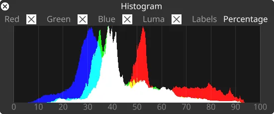
Histogram
Section titled “Histogram”Opens a live histogram, displaying the distribution of colour and luma of the current output.
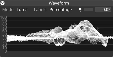
Waveform
Section titled “Waveform”Opens a live waveform diagram, displaying intensity of colour and luma across the current output.
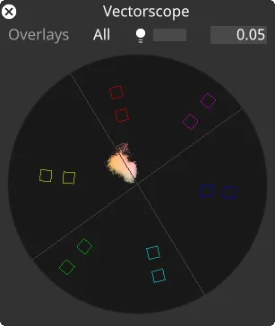
Vectorscope
Section titled “Vectorscope”Opens a live vectorscope, displaying the UV chroma channels on an x-y plot of the current output.
Options Specific to Quad SDI Card
Section titled “Options Specific to Quad SDI Card”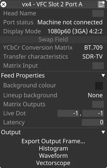
Swap Field
Section titled “Swap Field”For interlaced output, this button allows the user to swap between aligning the odd or even fields with the incoming genlock signal.
Colour Conversion Matrix
Section titled “Colour Conversion Matrix”Allows the user to define a colour conversion matrix (e.g. Rec.709, Rec.2020). This field is included in the SMPTE-425 video Payload Identifier. For outputting HDR video, Rec.2020 is required, combined with the Transfer Characteristics field described below.
Transfer Characteristics
Section titled “Transfer Characteristics”Allows the user to define the transfer characteristics (e.g. SDR, HLG, PQ). This field is included in the SMPTE-425 video Payload Identifier. For outputting HDR video, HLG or PQ is required, combined with the Rec.2020 Colour Conversion Matrix described above.
VFC Card Failures
Section titled “VFC Card Failures”When Designer starts, it will attempt to detect the VFC cards in the system and then initialise them ready for use. There are two stages at which this can fail:
-
VFC device detection and initialisation - Designer will detect the FTDI chip and attempt to read the model of VFC from it. If this fails, the card will be labelled as a VFC device failure. The card may need to be reseated or the firmware re-installed. Designer will not attempt to communicate with the card again until it’s restarted
-
VFC initialisation - Once Designer recognises the type of VFC, it will attempt to configure the hardware ready for use. If we fail at this stage, the card will be labelled as failing initialisation. In this case, Designer will prevent most use of the card, but an attempt to reset (currently available for HDMI only) can be made
In both these cases, the VFC border colour in the feeds screen will be red, and the Session Widget Status icons shown against that machine will indicate a VFC failure.
Options Specific to HDMI Card
Section titled “Options Specific to HDMI Card”Reset HDMI Card
Section titled “Reset HDMI Card”This button power cycles the HDMI card. This could help resolve issues such as an intermittent loss of card detection by Windows.
Options Specific to IP-VFC Card
Section titled “Options Specific to IP-VFC Card”There are a number of options specific to the IP-VFC card. For more details, please see this page.